
3. Ice Loads
Ice loads are an essential factor to consider for structures that interact with ice-covered waters, such as offshore wind turbines, oil rigs, and sea walls. These loads arise due to the movement and interaction of ice with structural elements and are influenced by environmental forces like wind, water currents, and temperature variations. The highly dynamic nature of ice loading means it cannot be treated as a simple static force; instead, calculations must account for both the energy and variability in ice behavior. Standards such as those written by the IEC (International Electrotechnical Commission) and ISO (International Organization for Standardization require ice load assessments to ensure the safety and integrity of structures exposed to ice forces.
Key Factors
Three critical parameters define ice loading conditions:
- Limit Energy: This describes the kinetic energy of the moving ice, driven by factors like velocity and mass.
- Limit Force: This is the maximum force within the adjacent ice field, often influenced by the properties of the ice sheet or field itself.
- Limit Stress: This is the point at which the ice fails upon contact with the structure. When limit energy and limit force are sufficiently large, limit stress becomes the controlling factor, governing the intensity and distribution of ice loads on the structure.
Ice interacts with structures through various failure mechanisms, including crushing, bending, buckling, and deformation. These mechanisms depend on both the structure’s design and the properties of the ice, with ice thickness, grain structure, and speed all contributing to different forms of structural impact.
Types of Ice Failure and Associated Loads
This chapter examines two primary modes of ice-structure interaction: crushing and flexural bending. Each of these is influenced, though differently, by ice thickness, structural geometry, and load dynamics, requiring distinct approaches to modeling and analysis.
Ice load models are built on a combination of physical theory and empirical data, the latter of which comes from both laboratory experiments and field observations. These models must capture the complexity of ice behavior, as the specific way ice fails upon interacting with a structure dictates the type and magnitude of load imposed. The failure mode of ice—and thus the loading mechanism—depends on a variety of factors, including:
- Ice thickness: Thicker ice can carry higher forces, often leading to crushing rather than brittle failure.
- Mechanical properties: The strength, stiffness, and ductility of ice change with temperature, salinity, and grain structure.
- Ice velocity: Faster-moving ice interacts differently with structures, leading to higher strain rates that can trigger brittle failure modes.
- Structure width: Wider structures experience more distributed loads, influencing the type of ice failure they induce.
From a materials science perspective, ice loading encompasses diverse failure mechanisms based on structural geometry and ice properties. Three common cases illustrate how different failure modes affect the loads:
- Thick, slow-moving ice on a vertical structure: This scenario often leads to ductile crushing of the ice, where the load is largely determined by the ice’s compressive strength.
- Thin or fast-moving ice: Here, ice may fail in brittle buckling rather than ductile crushing. The load imposed on the structure depends on the ice’s buckling strength and its ability to resist deformation at high strain rates.
- Conical-sided structures: When ice interacts with structures that have angled or conical sides, the ice often fails through bending rather than crushing. This load is governed by the ice’s flexural strength and depends less on ice thickness or velocity, making it relatively predictable under certain conditions.
Understanding these different cases allows engineers to anticipate how ice will behave based on structural design and environmental conditions, helping them tailor load models to the specific interaction mechanisms involved.
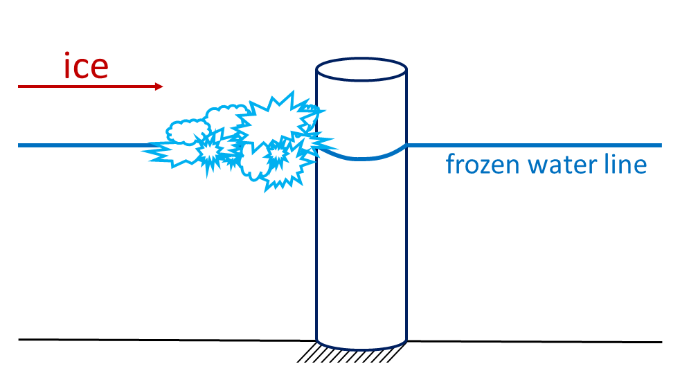
Ice Crushing Loads
Ice crushing occurs when ice makes direct contact with vertical or near-vertical structures, such as cylindrical supports for offshore platforms or sea walls. The nature and intensity of crushing loads depend on several factors:
- Grain structure and temperature of the ice.
- Brine content within the ice, affecting its brittleness.
- Ice thickness and contact area of the structure.
- Strain rate, which varies based on ice velocity and ranges from creep deformation to brittle failure.
The strain rate covers a large range of possibilities, from creep to plastic deformation to brittle behavior. The strain rate is dictated by the ice velocity, so any of the types of material deformations are quite possible. As such, loads from ice crushing can vary by several orders of magnitude.
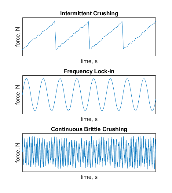
Ice crushing loads can be highly variable, exhibiting behaviors such as intermittent crushing, frequency lock-in, and continuous crushing:
- Intermittent Crushing: Appears as periodic loading cycles with sawtooth-like peaks. Load increases to a peak as the ice compresses and crushes, then rapidly declines. When the frequency of these pulses exceeds the natural frequency of the structure, resonance is avoided.
- Frequency Lock-In: Occurs when the natural frequency of the structure aligns with the frequency of ice loading, resulting in cyclical, potentially resonant loads. This scenario can lead to significant stress on the structure.
- Continuous Crushing: Involves a constant load with random variations, often characterized by a non-zero baseline load. Frequency spectra analysis is typically used to capture the dominant dynamic characteristics of continuous crushing.
These loads are depicted schematically in Figure 10.3.2, below.
These behaviors can vary significantly based on ice velocity, thickness, and structural response, with models often combining empirical data and physical theory to capture the range of loading effects. One widely used model, the Korzhavin equation (1971), is expressed as:

where F is the resulting ice load, h the ice thickness, w the width of the structure, and  the crushing strength of the ice. The values for can be determined by examining measured data, and usually range from 0.5 MPa for first-year ice up to 3.0 MPa for moving ice in the coldest months.
All k values are adjustment factors based on ice and structural characteristics. More specifically, constants  ,
,  , and
, and  are shape factor, contact factor, and an aspect ratio factor, respectively. A shape factor () value of 1.0 is used for rectangular structures, and 0.9 for circular shapes. The contact factor (
 ) adjusts the load prediction to account for the degree of contact between the ice and structure. When ice is moving, frozen, or locally thickened, equals 0.5, 1, and 1.5, respectively. Finally, accounts for the relative scale of the ice and structure computed with the equation below.

Flexural Loads
Flexural or bending failure occurs when ice interacts with structures with conical or angled sides. Here, the ice fails in bending rather than crushing, a process more dependent on the ice’s flexural strength than on crushing strength. Unlike ice crushing, flexural loads depend less on grain structure and ice temperature than ice crushing does. Flexural loads are also largely independent of strain rate. What does matter is the friction between ice and the conical structure.
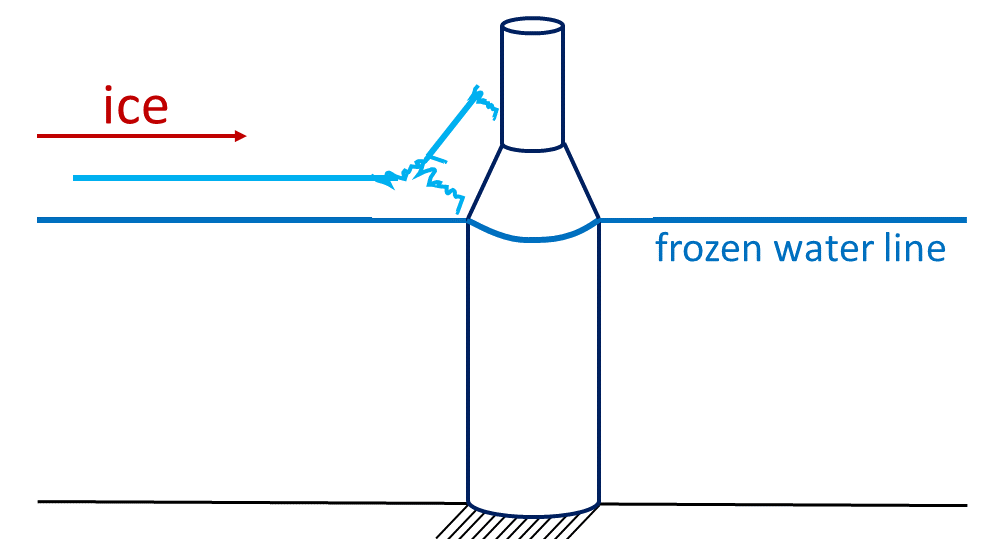
Flexural loads tend to be smaller than crushing loads due to the relatively easier bending of ice. This load type can vary dynamically, typically rising to a peak as the ice fractures, then reducing, often followed by periods of constant load. Designers use these characteristics to their advantage, creating angled or conical surfaces to reduce overall ice impact. This design strategy is commonly applied in boat hulls and at the ocean’s surface in cold-weather environments where offshore structures are likely to interact with ice.
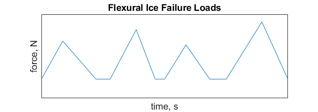
A schematic of the dynamic nature of flexural loads is shown in Figure 10.3.4 below. Here, the ice loads build up and then diminish, often followed by a brief period where the load is constant (shown here as straight lines). The amplitude and period of each peak is random, as opposed to the regular periods seen in the intermittent crushing graph.
A model often used for calculating flexural loads, the Croasdale model, aggregates various force components to represent the total flexural impact:

where each H term represents different load components based on ice and structural properties. First,  is the breaking load. The loads needed to move ice sheet and ice blocks through rubble pile are given by
  and
and  , respectively.
  accounts for the force need to lift the rubble pile, while
  considers what is need to rotate ice blocks at the bend in the structure.
Dynamic Analysis and Time Histories
Dynamic effects are crucial when evaluating ice loads due to the varied and unpredictable nature of ice failure. Different failure modes yield unique time histories:
- Periodic Time Histories: Represent consistent waveforms, with each cycle featuring a similar amplitude and period.
- Quasi-periodic Time Histories: Show more complex waveforms with multiple amplitudes and periods.
- Stochastic Time Histories: Arise in highly dynamic scenarios with random, irregular loads. Frequency spectrum analysis is typically used to interpret these loads and identify the dominant load frequencies.
The coupling between ice and the structure is a critical design consideration. Resonant interactions can lead to amplified loads, risking structural damage or failure. Additionally, dynamic ice loads can induce structural motion, increasing fatigue and potentially causing catastrophic failure if resonance occurs.
Summary and Design Considerations
In designing structures subject to ice loads, it is essential to account for the dynamic nature of ice interaction and the various failure modes. By designing for specific failure mechanisms—such as favoring bending over crushing—engineers can optimize structures to withstand ice impacts more effectively.
Standardized models, such as the Korzhavin equation for crushing and the Croasdale model for bending, provide valuable frameworks for estimating these loads. However, ongoing empirical data collection and adjustments to models are necessary due to the complex, dynamic characteristics of ice loads in real-world environments. By integrating empirical and theoretical approaches, engineers can better predict and mitigate the risks associated with ice-structure interactions, ensuring safe and durable designs for structures exposed to ice-covered waters.
References
McCoy, Timothy J., Brown, Thomas, and Byrne, Alex. Ice Load Project Final Technical Report. United States: N. p., 2014. Web. doi:10.2172/1303304.
