
7. Vortex Shedding and Induced Motion
In Section 2, we categorized hydrodynamic loads, placing current loads under static loads as an approximation. We simplified loads from current by treating them as constant forces over time, though in reality, uniform flow around objects often leads to dynamic, time-varying effects. In this section, we explore how steady, uniform flow past a bluff body (such as a cylinder) results in a time-dependent phenomenon known as vortex shedding.
Vortex Shedding
At higher flow velocities, certain shapes, especially bluff bodies like cylinders, create vortices, or swirling regions of fluid, in their wake. When flow conditions meet specific criteria, vortices form behind the body and shed in an alternating pattern, as shown in Figure 9.7.1. This alternating vortex pattern forms a Von Kármán vortex street, a sequence of swirling vortices on opposite sides of the flow centerline.
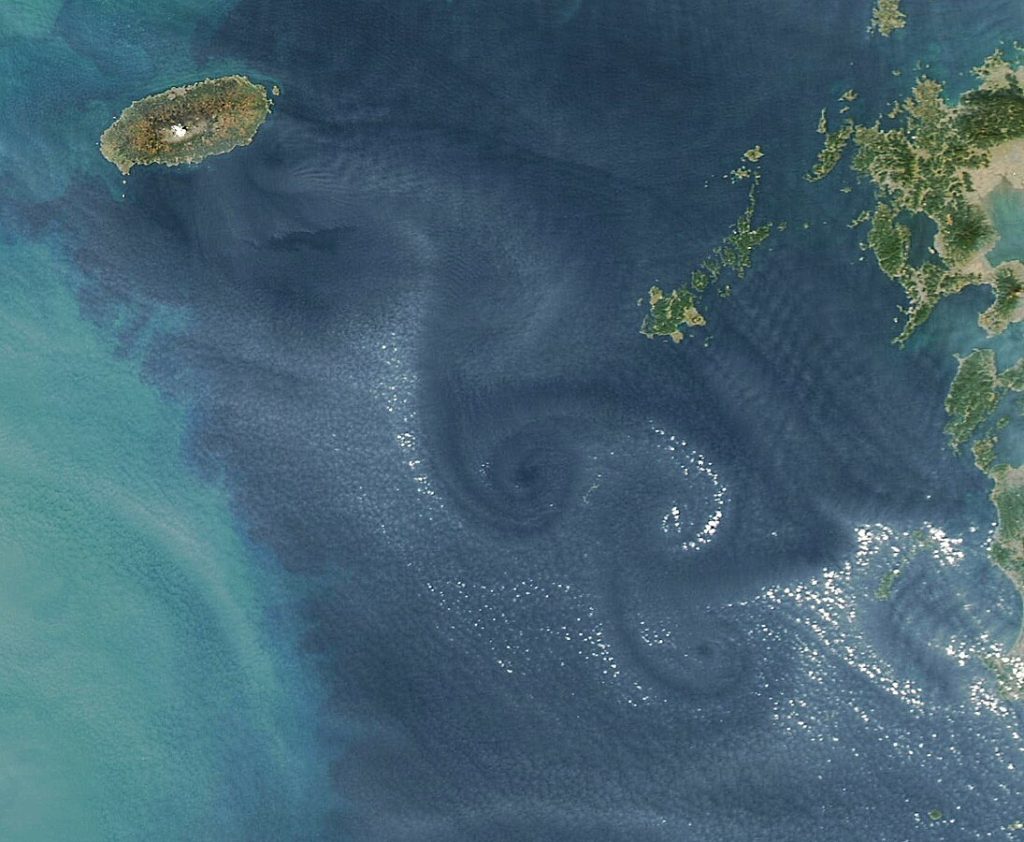
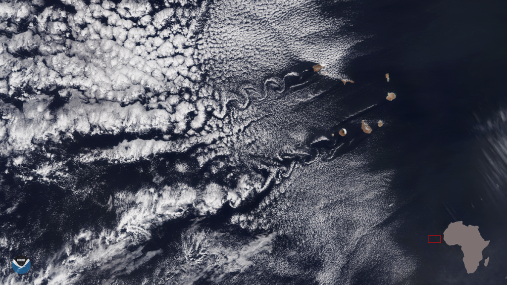
Von Kármán vortex streets are not just laboratory phenomena; they occur naturally. Examples include vortex shedding in the wakes of structures like dock pilings, offshore wind turbine monopiles, and oil rig support structures. Natural occurrences are also captured by satellites. Figure 9.7.2 shows a Von Kármán vortex street in clouds downstream of Jeju Island, Korea, while Figure 9.7.3 displays one downstream of the Cape Verde Islands, captured by the NOAA-20 satellite.
Regimes of Vortex Shedding
To generate Von Kármán vortex streets, specific conditions must be met, including a particular relationship between the flow velocity and body size. This relationship can be expressed using the Reynolds number (Re), which is given by:

where U is the flow velocity, D is the body diameter, and  is the fluid’s kinematic viscosity.
Using the Reynolds number, we can categorize six flow regimes for a cylinder, as summarized in Figure 9.7.4.
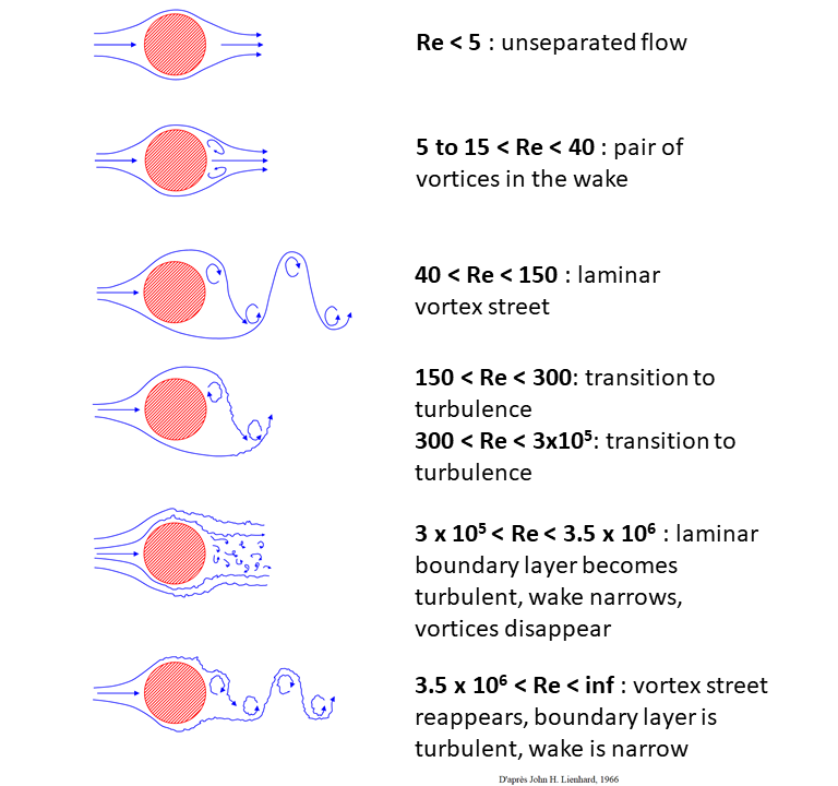
- Re < 5: Flow remains attached to the cylinder, and no vortices form.
- Re ~ 5–40: A pair of symmetric, stationary vortices form behind the cylinder, without shedding.
- Re ~ 40–150: A laminar vortex street emerges, with alternating vortices periodically shedding from each side of the cylinder.
- Re > 150: A turbulent vortex street develops in the wake, with laminar flow along the cylinder’s boundary layer.
- 30,000 < Re < 3,500,000: The boundary layer becomes turbulent, narrowing the wake, and periodic vortices disappear.
- Re > 3,500,000: The vortex street reappears, with turbulence in both the boundary layer and the wake.
Strouhal Number
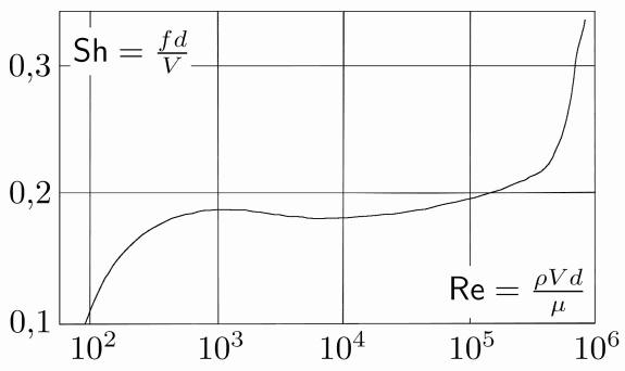
To quantify the frequency of vortex shedding, we use the Strouhal number (), defined as:

where f is the frequency of vortex shedding (Hz), D is the diameter of the body (m), and U is the flow velocity (m/s). Figure 9.7.5 illustrates the relationship between St and Re for a vertical cylinder. Up to a certain Reynolds number, St remains roughly constant at approximately 0.22, a value commonly used in engineering analyses.
(In some books or resources you may find that Sr or Sh are used.)
The relationship between Re and St is helpful for determining the frequency of vortex shedding, f.
Forces from Vortex Shedding
As ocean engineers, why should we care about vortex shedding (beyond appreciating the beauty of the fluid dynamics)? For one, the vortices create time-varying pressure fields that result in time-varying loads on the bodies. Second, these loads can lead to motion of the bodies, which we’ll explore in the next subsection.
As designers of potential offshore structures we need to be concerned about the impacts of the loads caused by periodic vortex shedding. The vortices are low pressure zones that alternate from side-to-side as they translate down the wake. These periodic low pressure zones result in periodic loads, as depicted in Figure 9.7.6 below.
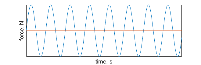
Periodic loads — or cyclical loads — introduce the issue of fatigue loading. The repetitive stress and strain on the body can lead to structural failure over extended periods of time, even if the magnitude of the periodic loading is small. (This is sometimes described in materials science courses with the example of gently bending a paperclip back and forth until it snaps.)
Induced Motion: Vortex Induced Vibrations
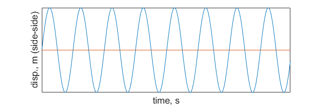
When the body is not fixed in place — perhaps because it is not rigidly mounted or the material is flexible — the periodic loading can lead to induced motion. The side-side loading on the body will cause it to move perpendicular to the flow direction. This effect is called vortex induced vibration (VIV), because sometimes the time period of oscillation is quite small.
The induced motion caused by vortex shedding is shown in Figure 9.7.7 where the object is displaced cyclically in the side-side direction, relative to the flow.
The cyclical motion of objects due to vortex shedding is another area of concern for a designer, again because of fatigue concerns, but also because of resonance. Resonance occurs when the body’s natural frequency matches the frequency of vortex shedding. Sometimes this effect is termed “lock-in.” It is a scenario that designers aim to avoid, as it leads to structure failure.
It is possible that you’ve observed resonance caused by VIV in the real world. For example, have you ever seen a power line vibrating wildly in the wind? If so, you were probably observing resonance of the power line, as the natural frequency of the structure matched the frequency of vortices shedding from the wind passing over the cylindrical line.
Suppressing Vortex Induced Vibrations
Various clever engineering tactics have been proposed to suppress vortex shedding, many of which have proven to be highly effective.
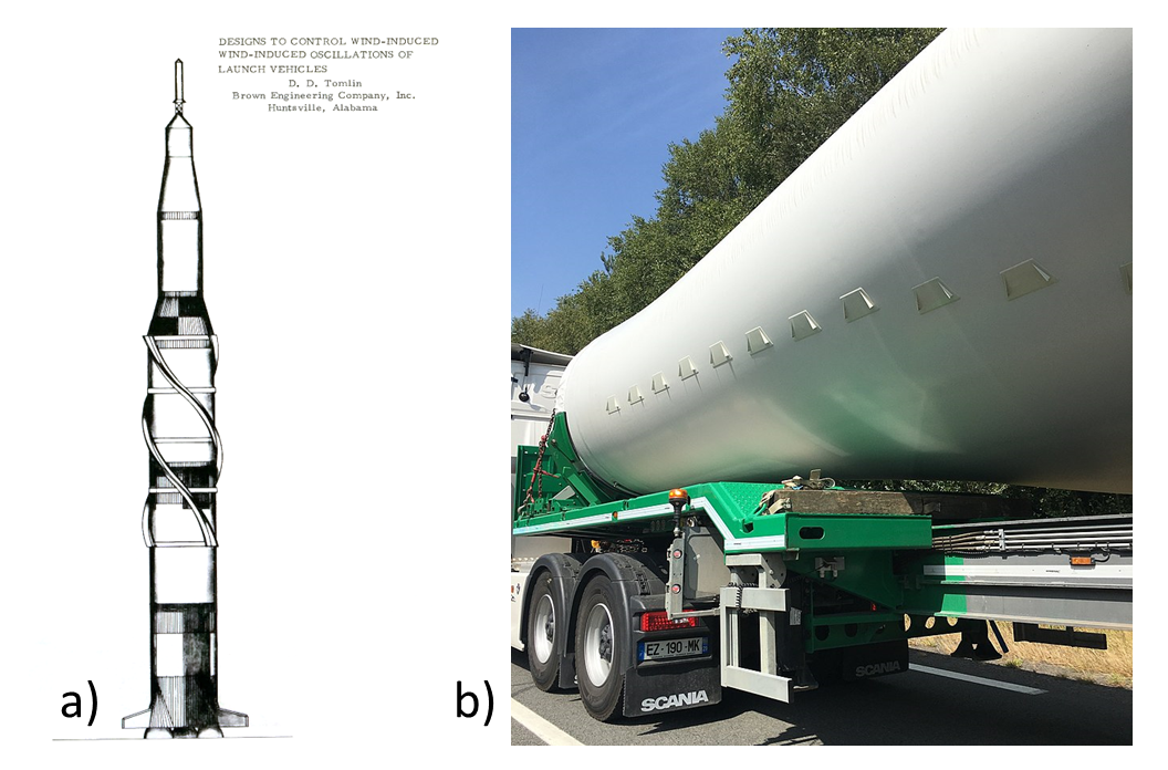
Many approaches involve simple alterations to the geometry of the body, for example adding helical strakes like the ones shown in Figure 9.7.8(a) Another example is the addition of small fin-like objects on the cylindrical root of a turbine blade, called turbulators, shown in Figure 9.7.8(b). Both of these geometric adjustments to the surface of cylinder accomplish the goal of disrupting the boundary layer and imparting turbulence into the flow. This ultimately helps to disrupt the periodic shedding of vortices in the wake, therefore prevent cyclic loading and the potential for VIV.
Another strategy for mitigating loads from VIV is to use a tuned mass damper (TMD). These devices work by moving in the direction opposite to the structure motion. For example, some skyscrapers have TMDs housed at the top to dampen motion caused by the wind, which can cause motion sickness to people in the building. TMDs have been proposed for use in wind turbines as well.
